advancing the mitigation of Climate Change and Global Warming through Geoengineering education and research
Space-based Geoengineering
Space-based geoengineering or climate engineering methods try to alleviate the effects of Climate Change by reducing the amount of sunlight that hits the Earth. The main goal of Space-based Geoengineering is to reduce global temperatures to pre-industrial/pre-fossil fuel levels. These approaches are generally considered to be a temporary solution because they do not address the root cause of Climate Change which is elevated levels of carbon dioxide in our atmosphere and biosphere.
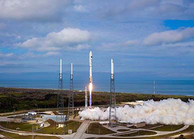
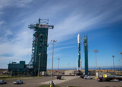
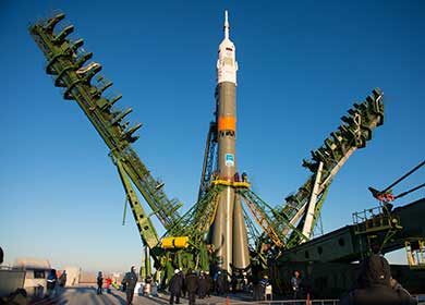
Space-based geoengineering methods are considered to be technically challenging and expensive in nature. To overcome the force of the Earth’s gravity and get materials into space generally requires the use of rockets. Other methods, however, have been proposed including using rail guns instead of rockets and manufacturing materials (e.g. 3D printing) using resources on the moon, which has one-sixth of the Earth’s gravity. Due to the complexity of these approaches, geoengineering researchers have suggested that it could take about 25 years to set up and deploy these solutions. Once deployed, these methods could be extremely effective in regulating global temperatures (Lenton and Vaughan, 2009) and protecting our biosphere.
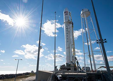
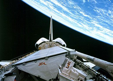
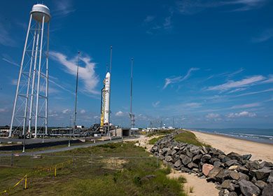
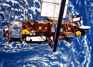
Space-based geoengineering approaches consist of the deployment of objects in space that can block or reflect sunlight away from the planet. Approaches include sunshades, reflectors or mirrors, and clouds of sun blocking particles. Researchers have proposed that these objects should be placed in orbit around the planet or at the L1 Lagrange point. The L1 Lagrange point is a specific location between the Earth and the Sun (about 1.5 million km from the Earth) where the gravity of the Earth and the Sun are approximately equal. At the L1 Lagrange point, very little energy would be needed to keep the objects in place (moved by the solar wind, etc.). Although placing a sun reflecting array at the L1 Lagrange point would be expensive and challenging, it is most likely well within our capability. On February 11, 2015, the U.S. National Oceanic and Atmospheric Administration launched the Deep Space Climate Observatory (DSCOVR) satellite which is currently located at the L1 Lagrange point (see NASA Goddard YouTube video below).
NOAA’s DSCOVR satellite one million miles away from the Earth at the L1 Lagrange point. Courtesy of NASA’s Goddard Space Flight Center.
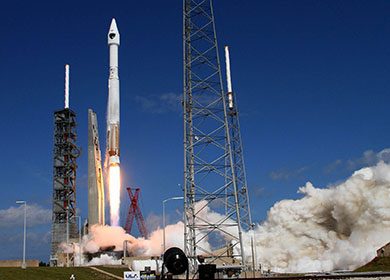

Angel (2006) proposed the use of very thin, transparent, meter-sized flyers or sunshades that would deflect sunlight away from the Earth. A 100,000 km-long cloud of 16 trillion flyers would be positioned 1.85 million kilometers away from the Earth at the L1 Lagrange point. This cloud of flyers would reduce sunlight to the planet by 1.8% mitigating Global Warming. Stacks of 800,000 flyers, that weigh about a gram each, would be launched into space using an electromagnetic coil or rail launch system. This $5 trillion solution (estimated cost in 2006) could be operational in 25 years and has a projected life span of 50 years.
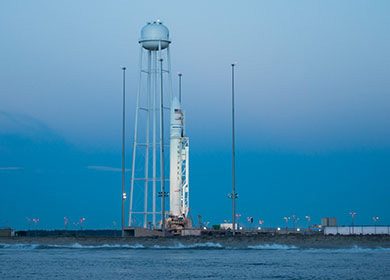
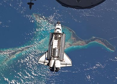
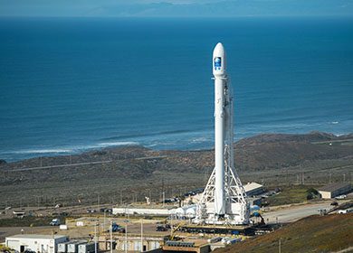
Ellery (2016) proposed manufacturing self-replicating robotic 3D printers (see the European Space Agency’s 3D printer YouTube video below) on the moon that would use materials on the moon (lunar in-situ resources) to produce the components needed to build multitudes of solar-powered spacecraft that could be deployed as a solar shield constellation. Ellery’s idea is to build a machine that can manufacture a copy of itself or another machine such as a solar shield module or spacecraft. The manufactured solar shield modules would be launched through the moon’s gravitational field and to the L1 Lagrange point using an electromagnetic launcher. Once in space, fully controllable solar modules would propel themselves with solar sails. NASA’s Resource Prospector mission (https://www.nasa.gov/resource-prospector), which is currently under development/pre-formulation, will conduct experimental mining operations and collect valuable data that could help advance this space-based geoengineering approach.
3D printing high performace engineered plastics for space-based applications. Courtesy of the European Space Agency.
References
Angel, R., 2006. Feasibility of cooling the Earth with a cloud of small spacecraft near the inner Lagrange point (L1). Proceedings of the National Academy of Sciences, 103(46), pp.17184-17189.
Ellery, A., 2016. Low-Cost Space-Based Geoengineering: An assessment based on self-replicating manufacturing of in-situ resources on the moon. World Academy of Science, Engineering and Technology International Journal of Environmental and Ecological Engineering, 10(2), pp.278-285.
Lenton, T.M. and Vaughan, N.E., 2009. The radiative forcing potential of different climate geoengineering options. Atmospheric Chemistry and Physics, 9(15), pp.5539-5561.